I am quite new to Motive and Optitrack. I did some test measurements of devices and humans to become familiar with the system. Currently I am working with Motive 1.10.
Now I have a couple of questions regarding rigid bodies, hopefully someone can help me
Many thanks in advance!
Question 1: Benefits of rigid bodies for marker tracking
If I create a rigid body before recording, the defined rigid body can improve the marker tracking ("Reconstructed Markers Only" = false, "Tracking Algorithm" = Ray based), right?
If I create a rigid body in an existing take, it will not have any positiv effect on marker tracking anymore?
Question 2: Renaming markers in rigid bodies
Is it possible to rename the markers of a rigid body in Motive 2.0?
Question 3: Experiments with rigid bodies (labeling of markers)
I created a rigid body with the name Arm3 consisting of 4 markers in an existing take. The take was recorded without rigid bodies or a marker set. As I wanted to define the positions of the markers within the rigid body, I manually labeled the markers. This was the result:
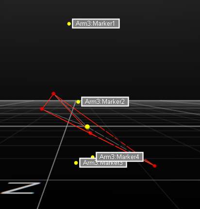
So the position of each marker within a rigid body is predefined by Motive? Is there a way to change/ define the positions/ oder of the marker in a rigid body manually?
If I apply "Reconstruct and Auto-label" on the take with the described rigid body Arm3, the orientation of the rigid body based on the 4 markers is correct. However, the rigid body "jumps away" at a certain point in the take but moves back into the correct position a few frames later:
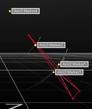
What could be the reason for the this "jump"?
If I manually label the markers of the rigid body Arm3 in a slightly different order compared to the auto-labeling, the body does not jump anymore:
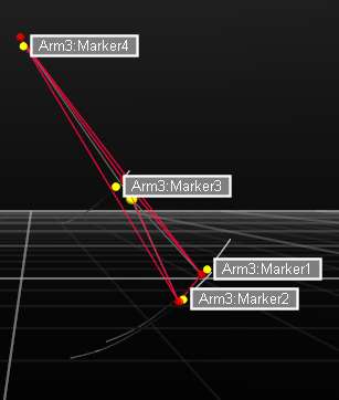
How does Motive determine the position of the markers within a rigid body? And how can I make sure, a rigid body does not jump?
Question 4: Define axis of rigid bodies
I am interested in the orientatation of rigid bodies and the angle between two rigid bodies. For this, it would be useful to manually define the rotation axis of rigid bodies. It is possible to set the coordinate system of a rigid body according to the global coordinate system. Unfortunately, this is too inaccurate, I would like to define the coordinate system based on the rigid body makers for example. Do you have a hint for me how to define rotation axes or how to calulate angles/ orientation of rigid bodies?
In the meantime I solved the "problem" by importing the coordinates of the markes as .csv into Matlab and calculate orientation/ angles of the desired segments.
Last Question 5: Calibration/ Re-calibration
If I reopen a calibrated project without changing anything on the hardware setup, do I need to perform a re-calibration and re-definition of the ground plane?
Sincerely,
sceu